ITF-1 (en)
ITF-1 was launched from Tanegashima Space Center on Feb, 28, 2014. It reentered the atmosphere on Jun, 29, 2014.
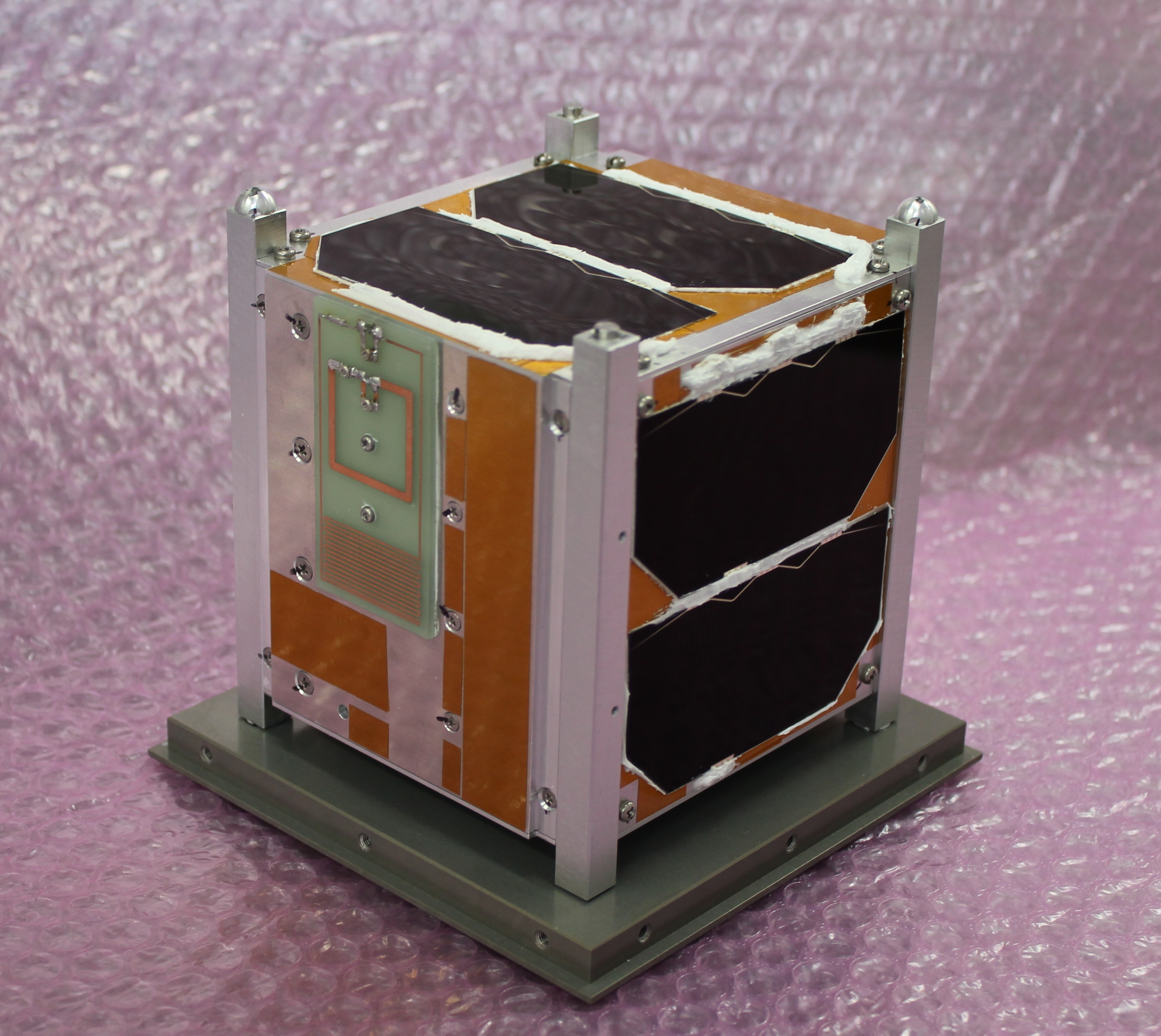
ITF-1 Flight Model
Missions
- The construction of "YUI" network
We construct the network to interact with people who have experience receiving the signal from ITF-1.
- The demonstration of ultra small antenna
We develop a new antenna without deployment mechanism and demonstrate in space.
- The demonstration of new microcomputer
We monitor FRAM microcomputer which has high radiation resistance, and others which have a good track performance in space.
Overview
Name
ITF-1(Imagine The Future-1)
Nickname
YUI("結")
Size
1U(110.5*108.0*111.5 mm)
Weight
1.24 kg
Frequency band
430MHz band/Morse (uplink)
430MHz, 144MHz band/F2D(DTMF) (downlink)
Height
400 km
Characteristic
Attitude control system
ITF-1 adopted the passive magnetic control method by earth magnetism. ITF-1 used a permanent magnet and a hysteresis damper.
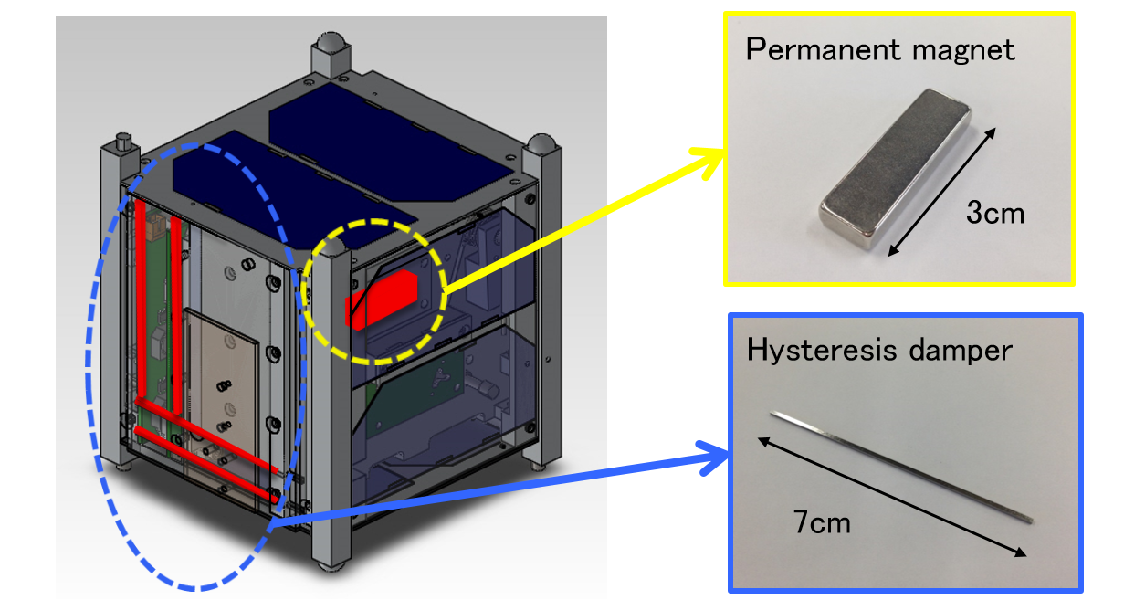
Attitude control components
- Permanent magnet
For a magnetic material in a magnetic field, it is worked magnetic torque along direction which a magnetic moment in a magnetic material and magnetic field are parallel. A magnetic moment of permanent magnet loaded on ITF-1 interferes with earth magnetism, and ITF-1 will be able to control attitude direction.
Overview of permanent magnet
Size
9.0 x 4.5 x 30.0 mm
Material
neodymium
Magnetization direction
30.0 mm direction
Surface fabricaion
Ni plating
Surface magnetic flux density
5070 G
Adsorption power
2.09 kg
Grade
N35
Limit temperature
150 deg C
- Hysteresis damper
ITF-1 will receive rotation kinetic energy from orbital deployer when it will be released. The rotation kinetic energy will constitute an obstacle to attitude control and ITF-1 needs to disperse it. However, since the atmosphere around ITF-1 is very dilute, a rotation kinetic energy dissipation rate is low and it takes a long time to stabilize attitude control. Therefore, ITF-1 uses the magnetic friction effect of hysteresis damper to disperse rotation kinetic energy and reduce the time to stabilize attitude control. We load two histerisis dampers on ITF-1.
Overview of hysterisis damper
Size
1.0 x 1.0 x 70.0 mm (prism)
material
PC permalloy (themally treate
Structure system
Structure team mainly handles the design and assembling of ITF-1.
Appearance of ITF-1
Material of ITF-1
Material
A6061P-T651, A7075-T7351
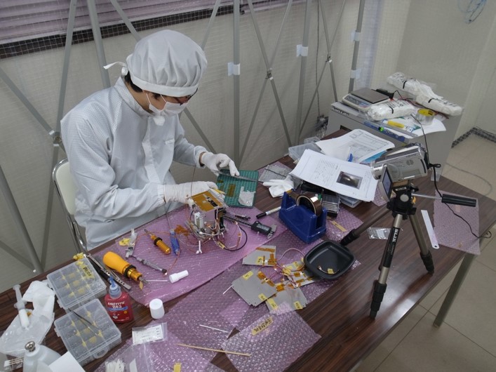
Assembly of ITF-1 FM (1)
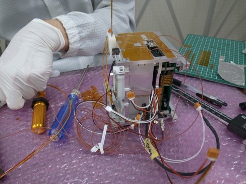
Assembly of ITF-1 FM (2)
Thermal control system
Thermal control team handles thermal analysis of ITF-1. We must prevent the temperature of all devices from exceeding limit temperature showed in following table. Thus, we analyze by method of panel point under high temperature worst condition and low temperature worst condition.
Range of limit temperature of devices in ITF-1
Name
Range[deg C]
Solar cell
-100~100
Battery
0~40
Radio module
-10~60
Main board
-20~60
Power supply board
-20~60
The result of analysis under high temperature worst condition and low temperature worst condition shows following figures. Thus, thermal design of ITF-1 covers the range of limit temperature of devices.
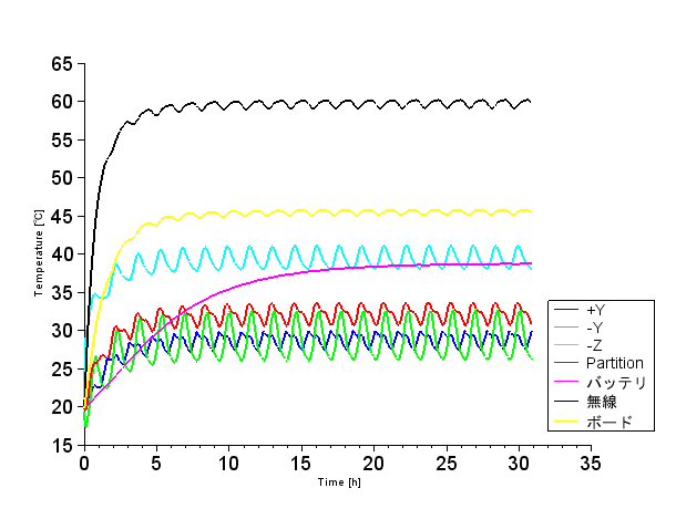
Result under high temperature worst condition
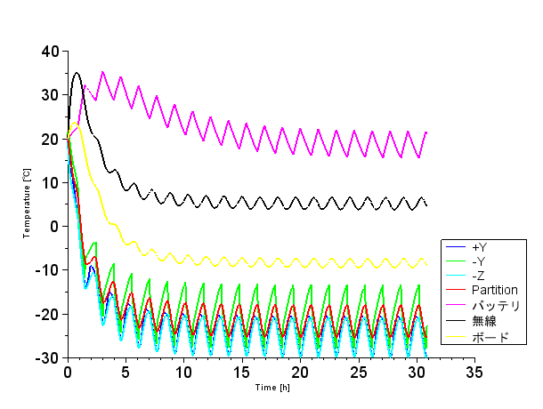
Result under low temperature worst condition
Power supply system
Power supply system consists of solar cells to generate electric power, battery, regulator to stabilize power supply part and power CPU to check discharge and charge. Satellite power supply bus adopts non-stabilized power supply system, in which solar cells or battery provide electric power and regulators stabilize voltage.
ITF-1 provides electric power generated by solar cells to devices and charging battery during sunshine. During shade, battery provides electric power to each devices instead.
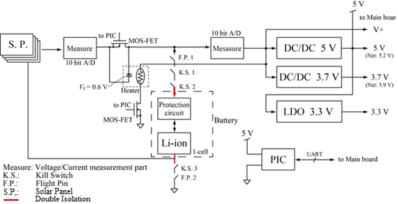
Power supply system block diagram
Solar cell
ITF-1 has solar panels on four faces. In order to secure enough electric power, ITF-1 adopts Triple Junction GaAs solar cells which have sufficiently high efficiency of electric power generation.
Overview of Solar cell
Average efficiency
29.1%
Voltage at Pmax
2379 mV
Current at Pmax
505 mA
Maximum power(Pmax)
1.2 W
Size
40 x 80 mm
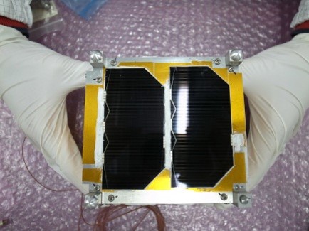
ITF-1 solar cells
Battery
ITF-1 adopts Li-ion battery. Solar cells generate electric power and charge battery during sunshine, and battery provides electric power to each devices only during shade.
ITF-1 has one Li-ion battery and stores it in battery box made of polyacetal resin to keep temperature. We design thermal condition to prevent the temperature of battery from exceeding 40 deg C and control the temperature by a heater to prevent it from falling below 0 deg C.
Power CPU
Power CPU adopts PIC16F877A. The works of Power CPU is followng below.
- After ITF-1 will be released from orbital deployer, kill switch will be open and ITF-1 will stand ready to transmit signal for 200 seconds.
- Power CPU monitor with Main CPU mutually. If Main CPU works abnormally, Power CPU reset Main CPU. If Abnormal works of Main CPU happen, such as no transmittion from Main CPU at regular time intervals and abnormal data from Main CPU, Power CPU sets FET in Main CPU to OFF and resets it. In addition, Power CPU checks the current consumed in Main CPU.
- If the current flowing to Main CPU increases due to latch-up, Power CPU resets Main CPU.
- When ITF-1 receives signal from the ground station by monopole antenna and ultra small antenna, Power CPU orders to downlink morse code and passes the current to a resistance in order to cut a gut that keeps monopole antenna from deploying.
Power consumption
Power consumption of each devices
Device
Power consumption[W]
Radio module(transmit)
0.78
Radio module(receive)
0.24
Radio module(standby)
0.07
Power CPU(PIC16F877A)
0.1
Main CPU(ATmega128)
0.14
Communication CPU(PIC16F877A)(normal)
0.035
Communication CPU(PIC16F877A)(sleep)
0.000025
Communication CPU(ATmega128)(normal)
0.15
Communication CPU(ATmega128)(sleep)
0.0
Communication CPU(MSP430FR5739)
0.003
Battery heater
0.8
Communication system
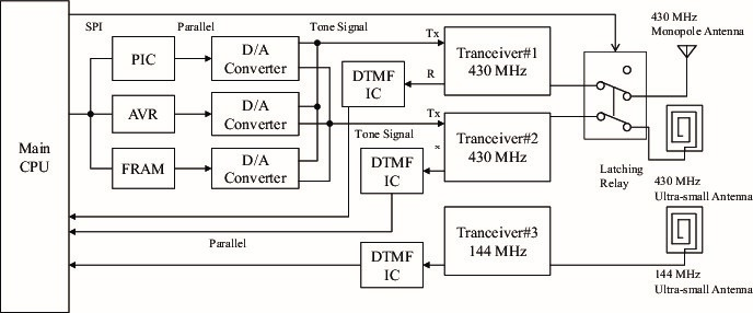
Communication system block diagram
Communication microcomputer
Name
Microcomputer
Main CPU
ATmega128
PIC
PIC16F877A
AVR
ATmega128
FRAM
MSP430FR5739
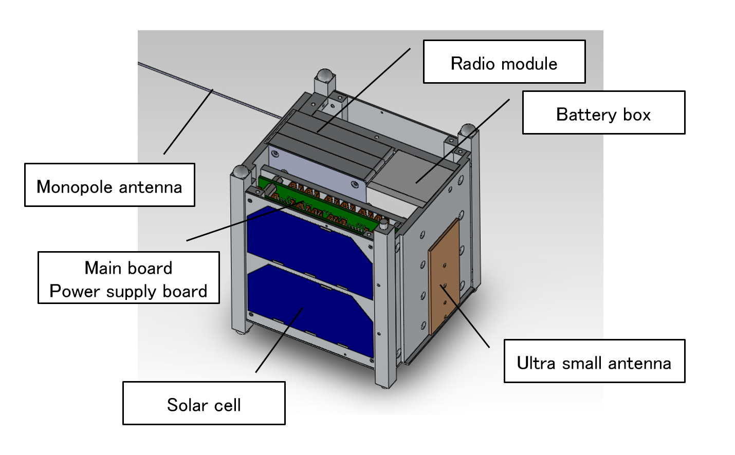
Radio module / Antenna
ITF-1 has three radio module, DJ-C7 made by ALINCO, and two radio modules for 430 MHz band and one radio module for 144 MHz band. Antennas are 430 MHz monopole antenna, 430 MHz ultra small antenna, and 144 MHz ultra small antenna.
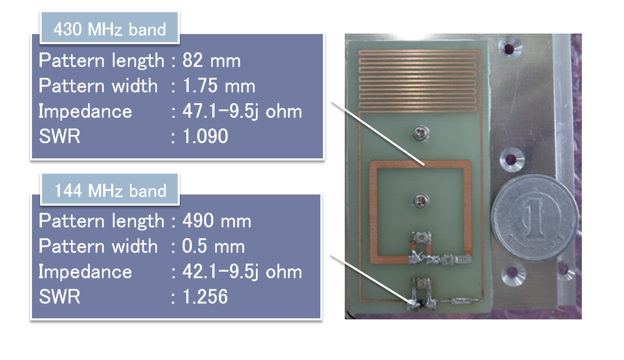
ultra small antenna